Structures 1 – Course Homework – Week 2
Themed Entertainment and Architecture
User note: Code change proposals to this chapter will be considered by the IBC – Structural Code
Development Committee during the 2016 (Group B) Code Development Cycle. See explanation on page iv.
The provisions of this chapter shall govern the structural design of buildings, structures and portions thereof regulated by this code.
The following terms are defined in Chapter 2:
ALLOWABLE STRESS DESIGN.
DEAD LOADS.
DESIGN STRENGTH.
DIAPHRAGM.
ESSENTIAL FACILITIES.
FABRIC PARTITION.
FACTORED LOAD.
HELIPAD.
ICE-SENSITIVE STRUCTURE.
IMPACT LOAD.
LIMIT STATE.
LIVE LOAD.
LIVE LOAD (ROOF).
LOAD AND RESISTANCE FACTOR DESIGN (LRFD).
LOAD EFFECTS.
LOAD FACTOR.
LOADS.
NOMINAL LOADS.
OTHER STRUCTURES.
PANEL (PART OF A STRUCTURE).
RESISTANCE FACTOR.
RISK CATEGORY.
STRENGTH, NOMINAL.
STRENGTH, REQUIRED.
STRENGTH DESIGN.
SUSCEPTIBLE BAY.
VEHICLE BARRIER.
NOTATIONS.
| D | = | Dead load. |
| Di | = | Weight of ice in accordance with Chapter 10 of ASCE 7. |
| E | = | Combined effect of horizontal and vertical earthquake induced forces as defined in Section 12.4.2 of ASCE 7. |
| F | = | Load due to fluids with well-defined pressures and maximum heights. |
| Fa | = | Flood load in accordance with Chapter 5 of ASCE 7. |
| H | = | Load due to lateral earth pressures, ground water pressure or pressure of bulk materials. |
| L | = | Roof live load greater than 20 psf (0.96 kN/m2) and floor live load. |
| Lr | = | Roof live load of 20 psf (0.96 kN/m2) or less. |
| R | = | Rain load. |
| S | = | Snow load. |
| T | = | Self-straining load. |
| Vasd | = | Nominal design wind speed (3-second gust), miles per hour (mph) (km/hr) where applicable. |
| Vult | = | Ultimate design wind speeds (3-second gust), miles per hour (mph) (km/hr) determined from Figure 1609.3(1), 1609.3(2), 1609.3(3) or ASCE 7. |
| W | = | Load due to wind pressure. |
| Wi | = | Wind-on-ice in accordance with Chapter 10 of ASCE 7. |
Construction documents shall show the size, section and relative locations of structural members with floor levels, column centers and offsets dimensioned. The design loads and other information pertinent to the structural design required by Sections 1603.1.1 through 1603.1.8 shall be indicated on the construction documents.
Exception: Construction documents for buildings constructed in accordance with the conventional light-frame construction provisions of Section 2308 shall indicate the following structural design information:
The uniformly distributed, concentrated and impact floor live load used in the design shall be indicated for floor areas. Use of live load reduction in accordance with Section 1607.10 shall be indicated for each type of live load used in the design.
The roof live load used in the design shall be indicated for roof areas (Section 1607.12).
The ground snow load, Pg, shall be indicated. In areas where the ground snow load, Pg, exceeds 10 pounds per square foot (psf) (0.479 kN/m2), the following additional information shall also be provided, regardless of whether snow loads govern the design of the roof:
The following information related to wind loads shall be shown, regardless of whether wind loads govern the design of the lateral force-resisting system of the structure:
The following information related to seismic loads shall be shown, regardless of whether seismic loads govern the design of the lateral force-resisting system of the structure:
The design load-bearing values of soils shall be shown on the construction documents.
For buildings located in whole or in part in flood hazard areas as established in Section 1612.3, the documentation pertaining to design, if required in Section 1612.5, shall be included and the following information, referenced to the datum on the community’s Flood Insurance Rate Map (FIRM), shall be shown, regardless of whether flood loads govern the design of the building:
Special loads that are applicable to the design of the building, structure or portions thereof shall be indicated along with the specified section of this code that addresses the special loading condition.
The dead load of rooftop-mounted photovoltaic panel systems, including rack support systems, shall be indicated on the construction documents.
Building, structures and parts thereof shall be designed and constructed in accordance with strength design, load and resistance factor design, allowable stress design, empirical design or conventional construction methods, as permitted by the applicable material chapters.
Buildings and other structures, and parts thereof, shall be designed and constructed to support safely the factored loads in load combinations defined in this code without exceeding the appropriate strength limit states for the materials of construction. Alternatively, buildings and other structures, and parts thereof, shall be designed and constructed to support safely the nominal loads in load combinations defined in this code without exceeding the appropriate specified allowable stresses for the materials of construction.
Loads and forces for occupancies or uses not covered in this chapter shall be subject to the approval of the building official.
Structural systems and members thereof shall be designed to have adequate stiffness to limit deflections and lateral drift. See Section 12.12.1 of ASCE 7 for drift limits applicable to earthquake loading.
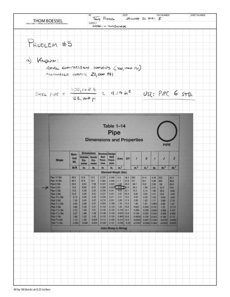
TABLE 1604.3
DEFLECTION LIMITSa, b, c, h, i
| CONSTRUCTION | L | S or W f | D + Ld, g |
| Roof members:e | |||
| Supporting plaster or stucco ceiling | l/360 | l/360 | l/240 |
| Supporting nonplaster ceiling | l/240 | l/240 | l/180 |
| Not supporting ceiling | l/180 | l/180 | l/120 |
| Floor members | l/360 | — | l/240 |
| Exterior walls: | |||
| With plaster or stucco finishes | — | l/360 | — |
| With other brittle finishes | — | l/240 | — |
| With flexible finishes | — | l/120 | — |
| Interior partitions:b | |||
| With plaster or stucco finishes | l/360 | — | — |
| With other brittle finishes | l/240 | — | — |
| With flexible finishes | l/120 | — | — |
| Farm buildings | — | — | l/180 |
| Greenhouses | — | — | l/120 |
For SI: 1 foot = 304.8 mm.
The deflections of structural members shall not exceed the more restrictive of the limitations of Sections 1604.3.2 through 1604.3.5 or that permitted by Table 1604.3.
The deflection of reinforced concrete structural members shall not exceed that permitted by ACI 318.
The deflection of steel structural members shall not exceed that permitted by AISC 360, AISI S100, ASCE 8, SJI CJ, SJI JG, SJI K or SJI LH/DLH, as applicable.
The deflection of masonry structural members shall not exceed that permitted by TMS 402/ACI 530/ASCE 5.
The deflection of aluminum structural members shall not exceed that permitted by AA ADM1.
The deflection limits of Section 1604.3.1 shall be used unless more restrictive deflection limits are required by a referenced standard for the element or finish material.
Load effects on structural members and their connections shall be determined by methods of structural analysis that take into account equilibrium, general stability, geometric compatibility and both short- and long-term material properties.
Members that tend to accumulate residual deformations under repeated service loads shall have included in their analysis the added eccentricities expected to occur during their service life.
Any system or method of construction to be used shall be based on a rational analysis in accordance with well-established principles of mechanics. Such analysis shall result in a system that provides a complete load path capable of transferring loads from their point of origin to the load-resisting elements.
The total lateral force shall be distributed to the various vertical elements of the lateral force-resisting system in proportion to their rigidities, considering the rigidity of the horizontal bracing system or diaphragm. Rigid elements assumed not to be a part of the lateral force-resisting system are permitted to be incorporated into buildings provided their effect on the action of the system is considered and provided for in the design. A diaphragm is rigid for the purpose of distribution of story shear and torsional moment when the lateral deformation of the diaphragm is less than or equal to two times the average story drift. Where required by ASCE 7, provisions shall be made for the increased forces induced on resisting elements of the structural system resulting from torsion due to eccentricity between the center of application of the lateral forces and the center of rigidity of the lateral force-resisting system.
Every structure shall be designed to resist the overturning effects caused by the lateral forces specified in this chapter. See Section 1609 for wind loads, Section 1610 for lateral soil loads and Section 1613 for earthquake loads.
Each building and structure shall be assigned a risk category in accordance with Table 1604.5. Where a referenced standard specifies an occupancy category, the risk category shall not be taken as lower than the occupancy category specified therein. Where a referenced standard specifies that the assignment of a risk category be in accordance with ASCE 7, Table 1.5-1, Table 1604.5 shall be used in lieu of ASCE 7, Table 1.5-1.
TABLE 1604.5
RISK CATEGORY OF BUILDINGS AND OTHER STRUCTURES
| RISK CATEGORY | NATURE OF OCCUPANCY |
| I | Buildings and other structures that represent a low hazard to human life in the event of failure, including but not limited to: •Agricultural facilities.•Certain temporary facilities.•Minor storage facilities. |
| II | Buildings and other structures except those listed in Risk Categories I, III and IV. |
| III | Buildings and other structures that represent a substantial hazard to human life in the event of failure, including but not limited to: •Buildings and other structures whose primary occupancy is public assembly with an occupant load greater than 300.•Buildings and other structures containing Group E occupancies with an occupant load greater than 250.•Buildings and other structures containing educational occupancies for students above the 12th grade with an occupant load greater than 500.•Group I-2 occupancies with an occupant load of 50 or more resident care recipients but not having surgery or emergency treatment facilities.•Group I-3 occupancies.•Any other occupancy with an occupant load greater than 5,000.a•Power-generating stations, water treatment facilities for potable water, wastewater treatment facilities and other public utility facilities not included in Risk Category IV.•Buildings and other structures not included in Risk Category IV containing quantities of toxic or explosive materials that:Exceed maximum allowable quantities per control area as given in Table 307.1(1) or 307.1(2) or per outdoor control area in accordance with the International Fire Code; andAre sufficient to pose a threat to the public if released.b |
| IV | Buildings and other structures designated as essential facilities, including but not limited to: •Group I-2 occupancies having surgery or emergency treatment facilities.•Fire, rescue, ambulance and police stations and emergency vehicle garages.•Designated earthquake, hurricane or other emergency shelters.•Designated emergency preparedness, communications and operations centers and other facilities required for emergency response.•Power-generating stations and other public utility facilities required as emergency backup facilities for Risk Category IV structures.•Buildings and other structures containing quantities of highly toxic materials that:Exceed maximum allowable quantities per control area as given in Table 307.1(2) or per outdoor control area in accordance with the International Fire Code; andAre sufficient to pose a threat to the public if released.b•Aviation control towers, air traffic control centers and emergency aircraft hangars.•Buildings and other structures having critical national defense functions.•Water storage facilities and pump structures required to maintain water pressure for fire suppression. |
Where a building or structure is occupied by two or more occupancies not included in the same risk category, it shall be assigned the classification of the highest risk category corresponding to the various occupancies. Where buildings or structures have two or more portions that are structurally separated, each portion shall be separately classified. Where a separated portion of a building or structure provides required access to, required egress from or shares life safety components with another portion having a higher risk category, both portions shall be assigned to the higher risk category.
The building official is authorized to require an engineering analysis or a load test, or both, of any construction whenever there is reason to question the safety of the construction for the intended occupancy. Engineering analysis and load tests shall be conducted in accordance with Section 1708.
Materials and methods of construction that are not capable of being designed by approved engineering analysis or that do not comply with the applicable referenced standards, or alternative test procedures in accordance with Section 1707, shall be load tested in accordance with Section 1719.
Buildings and other structures, and portions thereof, shall be provided with anchorage in accordance with Sections 1604.8.1 through 1604.8.3, as applicable.
Anchorage of the roof to walls and columns, and of walls and columns to foundations, shall be provided to resist the uplift and sliding forces that result from the application of the prescribed loads.
Walls that provide vertical load-bearing resistance or lateral shear resistance for a portion of the structure shall be anchored to the roof and to all floors and members that provide lateral support for the wall or that are supported by the wall. The connections shall be capable of resisting the horizontal forces specified in Section 1.4.5 of ASCE 7 for walls of structures assigned to Seismic Design Category A and to Section 12.11 of ASCE 7 for walls of structures assigned to all other seismic design categories. Required anchors in masonry walls of hollow units or cavity walls shall be embedded in a reinforced grouted structural element of the wall. See Sections 1609 for wind design requirements and 1613 for earthquake design requirements.
Where supported by attachment to an exterior wall, decks shall be positively anchored to the primary structure and designed for both vertical and lateral loads as applicable. Such attachment shall not be accomplished by the use of toenails or nails subject to withdrawal. Where positive connection to the primary building structure cannot be verified during inspection, decks shall be self-supporting. Connections of decks with cantilevered framing members to exterior walls or other framing members shall be designed for both of the following:
Structural members, systems, components and cladding shall be designed to resist forces due to earthquakes and wind, with consideration of overturning, sliding and uplift. Continuous load paths shall be provided for transmitting these forces to the foundation. Where sliding is used to isolate the elements, the effects of friction between sliding elements shall be included as a force.
Lateral force-resisting systems shall meet seismic detailing requirements and limitations prescribed in this code and ASCE 7, excluding Chapter 14 and Appendix 11A, even when wind load effects are greater than seismic load effects.
Buildings and other structures and portions thereof shall be designed to resist:
Applicable loads shall be considered, including both earthquake and wind, in accordance with the specified load combinations. Each load combination shall also be investigated with one or more of the variable loads set to zero.
Where the load combinations with overstrength factor in Section 12.4.3.2 of ASCE 7 apply, they shall be used as follows:
Regardless of which load combinations are used to design for strength, where overall structure stability (such as stability against overturning, sliding, or buoyancy) is being verified, use of the load combinations specified in Section 1605.2 or 1605.3 shall be permitted. Where the load combinations specified in Section 1605.2 are used, strength reduction factors applicable to soil resistance shall be provided by a registered design professional. The stability of retaining walls shall be verified in accordance with Section 1807.2.3.
Where strength design or load and resistance factor design is used, buildings and other structures, and portions thereof, shall be designed to resist the most critical effects resulting from the following combinations of factored loads:
 (Equation 16-1)
 (Equation 16-2)
 (Equation 16-3)
 (Equation 16-4)
 (Equation 16-5)
 (Equation 16-6)
 (Equation 16-7)
where:
| f1 | = | 1 for places of public assembly live loads in excess of 100 pounds per square foot (4.79 kN/m2), and parking garages; and 0.5 for other live loads. |
| f2 | = | 0.7 for roof configurations (such as saw tooth) that do not shed snow off the structure, and 0.2 for other roof configurations. |
Exceptions:
Where flood loads, Fa, are to be considered in the design, the load combinations of Section 2.3.3 of ASCE 7 shall be used. Where self-straining loads, T, are considered in design, their structural effects in combination with other loads shall be determined in accordance with Section 2.3.5 of ASCE 7. Where an ice-sensitive structure is subjected to loads due to atmospheric icing, the load combinations of Section 2.3.4 of ASCE 7 shall be considered.
Where allowable stress design (working stress design), as permitted by this code, is used, structures and portions thereof shall resist the most critical effects resulting from the following combinations of loads:
 (Equation 16-8)
 (Equation 16-9)
 (Equation 16-10)
 (Equation 16-11)
 (Equation 16-12)
 (Equation 16-13)
 (Equation 16-14)
 (Equation 16-15)
 (Equation 16-16)
Exceptions:
Increases in allowable stresses specified in the appropriate material chapter or the referenced standards shall not be used with the load combinations of Section 1605.3.1, except that increases shall be permitted in accordance with Chapter 23.
Where flood loads, Fa, are to be considered in design, the load combinations of Section 2.4.2 of ASCE 7 shall be used. Where self-straining loads, T, are considered in design, their structural effects in combination with other loads shall be determined in accordance with Section 2.4.4 of ASCE 7. Where an ice-sensitive structure is subjected to loads due to atmospheric icing, the load combinations of Section 2.4.3 of ASCE 7 shall be considered.
In lieu of the basic load combinations specified in Section 1605.3.1, structures and portions thereof shall be permitted to be designed for the most critical effects resulting from the following combinations. When using these alternative basic load combinations that include wind or seismic loads, allowable stresses are permitted to be increased or load combinations reduced where permitted by the material chapter of this code or the referenced standards. For load combinations that include the counteracting effects of dead and wind loads, only two-thirds of the minimum dead load likely to be in place during a design wind event shall be used. When using allowable stresses that have been increased or load combinations that have been reduced as permitted by the material chapter of this code or the referenced standards, where wind loads are calculated in accordance with Chapters 26 through 31 of ASCE 7, the coefficient (ω) in the following equations shall be taken as 1.3. For other wind loads, (ω) shall be taken as 1. When allowable stresses have not been increased or load combinations have not been reduced as permitted by the material chapter of this code or the referenced standards, (ω) shall be taken as 1. When using these alternative load combinations to evaluate sliding, overturning and soil bearing at the soil-structure interface, the reduction of foundation overturning from Section 12.13.4 in ASCE 7 shall not be used. When using these alternative basic load combinations for proportioning foundations for loadings, which include seismic loads, the vertical seismic load effect, Ev, in Equation 12.4-4 of ASCE 7 is permitted to be taken equal to zero.
 (Equation 16-17)
 (Equation 16-18)
 (Equation 16-19)
 (Equation 16-20)
 (Equation 16-21)
 (Equation 16-22)
Exceptions:
Where F, H or T are to be considered in the design, each applicable load shall be added to the combinations specified in Section 1605.3.2. Where self-straining loads, T, are considered in design, their structural effects in combination with other loads shall be determined in accordance with Section 2.4.4 of ASCE 7.
Dead loads are those loads defined in Chapter 2 of this code. Dead loads shall be considered permanent loads.
For purposes of design, the actual weights of materials of construction and fixed service equipment shall be used. In the absence of definite information, values used shall be subject to the approval of the building official.
Live loads are those loads defined in Chapter 2 of this code.
TABLE 1607.1
MINIMUM UNIFORMLY DISTRIBUTED LIVE LOADS, L0, AND MINIMUM CONCENTRATED LIVE LOADSg
| OCCUPANCY OR USE | UNIFORM (psf) | CONCENTRATED (pounds) |
| 1. Apartments (see residential) | — | — |
| 2. Access floor systems | ||
| Office use | 50 | 2,000 |
| Computer use | 100 | 2,000 |
| 3. Armories and drill rooms | 150m | — |
| 4. Assembly areas | — | |
| Fixed seats (fastened to floor) | 60m | |
| Follow spot, projections and control rooms | 50 | |
| Lobbies | 100m | |
| Movable seats | 100m | |
| Stage floors | 150m | |
| Platforms (assembly) | 100m | |
| Other assembly areas | 100m | |
| 5. Balconies and decksh | Same as occupancy served | — |
| 6. Catwalks | 40 | 300 |
| 7. Cornices | 60 | — |
| 8. Corridors | — | |
| First floor | 100 | |
| Other floors | Same as occupancy served except as indicated | |
| 9. Dining rooms and restaurants | 100m | — |
| 10. Dwellings (see residential) | — | — |
| 11. Elevator machine room and control room grating (on area of 2 inches by 2 inches) | — | 300 |
| 12. Finish light floor plate construction (on area of 1 inch by 1 inch) | — | 200 |
| 13. Fire escapes | 100 | — |
| On single-family dwellings only | 40 | |
| 14. Garages (passenger vehicles only) | 40m | Note a |
| Trucks and buses | See Section 1607.7 | |
| 15. Handrails, guards and grab bars | See Section 1607.8 | |
| 16. Helipads | See Section 1607.6 | |
| 17. Hospitals | ||
| Corridors above first floor | 80 | 1,000 |
| Operating rooms, laboratories | 60 | 1,000 |
| Patient rooms | 40 | 1,000 |
| 18. Hotels (see residential) | — | — |
| 19. Libraries | ||
| Corridors above first floor | 80 | 1,000 |
| Reading rooms | 60 | 1,000 |
| Stack rooms | 150b, m | 1,000 |
| 20. Manufacturing | ||
| Heavy | 250m | 3,000 |
| Light | 125m | 2,000 |
| 21. Marquees, except one-and two-family dwellings | 75 | — |
| 22. Office buildings | ||
| Corridors above first floor | 80 | 2,000 |
| File and computer rooms shall be designed for heavier loads based on anticipated occupancy | — | — |
| Lobbies and first-floor corridors | 100 | 2,000 |
| Offices | 50 | 2,000 |
| 23. Penal institutions | — | |
| Cell blocks | 40 | |
| Corridors | 100 | |
| 24. Recreational uses: | — | |
| Bowling alleys, poolrooms and similar uses | 75m | |
| Dance halls and ballrooms | 100m | |
| Gymnasiums | 100m | |
| Ice skating rink | 250m | |
| Reviewing stands, grandstands and bleachers | 100c, m | |
| Roller skating rink | 100m | |
| Stadiums and arenas with fixed seats (fastened to floor) | 60c, m | |
| 25. Residential | — | |
| One- and two-family dwellings | ||
| Uninhabitable attics without storagei | 10 | |
| Uninhabitable attics with storagei, j, k | 20 | |
| Habitable attics and sleeping areask | 30 | |
| Canopies, including marquees | 20 | |
| All other areas | 40 | |
| Hotels and multifamily dwellings | ||
| Private rooms and corridors serving them | 40 | |
| Public roomsm and corridors serving them | 100 | |
| 26. Roofs | ||
| All roof surfaces subject to maintenance workers | 300 | |
| Awnings and canopies: | ||
| Fabric construction supported by a skeleton structure | 5 Nonreducible | |
| All other construction, except one-and two-family dwellings | 20 | |
| Ordinary flat, pitched, and curved roofs (that are not occupiable) | 20 | |
| Primary roof members exposed to a work floor | ||
| Single panel point of lower chord of roof trusses or any point along primary structural members supporting roofs over manufacturing, storage warehouses, and repair garages | 2,000 | |
| All other primary roof members | 300 | |
| Occupiable roofs: | ||
| Roof gardens | 100 | |
| Assembly areas | 100m | |
| All other similar areas | Note 1 | Note 1 |
| 27. Schools | ||
| Classrooms | 40 | 1,000 |
| Corridors above first floor | 80 | 1,000 |
| First-floor corridors | 100 | 1,000 |
| 28. Scuttles, skylight ribs and accessible ceilings | — | 200 |
| 29. Sidewalks, vehicular driveways and yards, subject to trucking | 250d, m | 8,000e |
| 30. Stairs and exits | ||
| One- and two-family dwellings | 40 | 300f |
| All other | 100 | 300f |
| 31. Storage warehouses (shall be designed for heavier loads if required for anticipated storage) | — | |
| Heavy | 250m | |
| Light | 125m | |
| 32. Stores | ||
| Retail | ||
| First floor | 100 | 1,000 |
| Upper floors | 75 | 1,000 |
| Wholesale, all floors | 125m | 1,000 |
| 33. Vehicle barriers | See Section 1607.8.3 | |
| 34. Walkways and elevated platforms (other than exitways) | 60 | — |
| 35. Yards and terraces, pedestrians | 100m | — |
For SI: 1 inch = 25.4 mm, 1 square inch = 645.16 mm2,
1 square foot = 0.0929 m2,
1 pound per square foot = 0.0479 kN/m2, 1 pound = 0.004448 kN,
1 pound per cubic foot = 16 kg/m3.
For occupancies or uses not designated in Table 1607.1, the live load shall be determined in accordance with a method approved by the building official.
The live loads used in the design of buildings and other structures shall be the maximum loads expected by the intended use or occupancy but shall in no case be less than the minimum uniformly distributed live loads given in Table 1607.1.
Floors and other similar surfaces shall be designed to support the uniformly distributed live loads prescribed in Section 1607.3 or the concentrated live loads, given in Table 1607.1, whichever produces the greater load effects. Unless otherwise specified, the indicated concentration shall be assumed to be uniformly distributed over an area of 21/2 feet by 21/2 feet (762 mm by 762 mm) and shall be located so as to produce the maximum load effects in the structural members.
In office buildings and in other buildings where partition locations are subject to change, provisions for partition weight shall be made, whether or not partitions are shown on the construction documents, unless the specified live load is 80 psf (3.83 kN/m2) or greater. The partition load shall be not less than a uniformly distributed live load of 15 psf (0.72 kN/m2).
Helipads shall be designed for the following live loads:
Landing areas designed for a design basis helicopter with maximum take-off weight of 3,000-pounds (13.35 kN) shall be identified with a 3,000 pound (13.34 kN) weight limitation. The landing area weight limitation shall be indicated by the numeral “3” (kips) located in the bottom right corner of the landing area as viewed from the primary approach path. The indication for the landing area weight limitation shall be a minimum 5 feet (1524 mm) in height.
Floors and other surfaces that are intended to support vehicle loads greater than a 10,000-pound (4536 kg) gross vehicle weight rating shall comply with Sections 1607.7.1 through 1607.7.5.
Where any structure does not restrict access for vehicles that exceed a 10,000-pound (4536 kg) gross vehicle weight rating, those portions of the structure subject to such loads shall be designed using the vehicular live loads, including consideration of impact and fatigue, in accordance with the codes and specifications required by the jurisdiction having authority for the design and construction of the roadways and bridges in the same location of the structure.
Where a structure or portions of a structure are accessed and loaded by fire department access vehicles and other similar emergency vehicles, the structure shall be designed for the greater of the following loads:
Garages designed to accommodate vehicles that exceed a 10,000-pound (4536 kg) gross vehicle weight rating, shall be designed using the live loading specified by Section 1607.7.1. For garages the design for impact and fatigue is not required.
Exception: The vehicular live loads and load placement are allowed to be determined using the actual vehicle weights for the vehicles allowed onto the garage floors, provided such loads and placement are based on rational engineering principles and are approved by the building official, but shall not be less than 50 psf (2.9 kN/m2). This live load shall not be reduced.
Where a structure is intended to have forklifts or other movable equipment present, the structure shall be designed for the total vehicle or equipment load and the individual wheel loads for the anticipated vehicles as specified by the owner of the facility. These loads shall be posted in accordance with Section 1607.7.5.
Impact loads and fatigue loading shall be considered in the design of the supporting structure. For the purposes of design, the vehicle and wheel loads shall be increased by 30 percent to account for impact.
The maximum weight of vehicles allowed into or on a garage or other structure shall be posted by the owner or the owner’s authorized agent in accordance with Section 106.1.
Handrails, guards, grab bars, accessible seats, accessible benches and vehicle barriers shall be designed and constructed for the structural loading conditions set forth in this section.
Handrails and guards shall be designed to resist a linear load of 50 pounds per linear foot (plf) (0.73 kN/m) in accordance with Section 4.5.1 of ASCE 7. Glass handrail assemblies and guards shall also comply with Section 2407.
Exceptions:
Handrails and guards shall be designed to resist a concentrated load of 200 pounds (0.89 kN) in accordance with Section 4.5.1 of ASCE 7.
Intermediate rails (all those except the handrail), balusters and panel fillers shall be designed to resist a concentrated load of 50 pounds (0.22 kN) in accordance with Section 4.5.1 of ASCE 7.
Grab bars, shower seats and dressing room bench seats shall be designed to resist a single concentrated load of 250 pounds (1.11 kN) applied in any direction at any point on the grab bar or seat so as to produce the maximum load effects.
Vehicle barriers for passenger vehicles shall be designed to resist a concentrated load of 6,000 pounds (26.70 kN) in accordance with Section 4.5.3 of ASCE 7. Garages accommodating trucks and buses shall be designed in accordance with an approved method that contains provisions for traffic railings.
The live loads specified in Sections 1607.3 through 1607.8 shall be assumed to include adequate allowance for ordinary impact conditions. Provisions shall be made in the structural design for uses and loads that involve unusual vibration and impact forces.
Members, elements and components subject to dynamic loads from elevators shall be designed for impact loads and deflection limits prescribed by ASME A17.1/CSA B44.
For the purpose of design, the weight of machinery and moving loads shall be increased as follows to allow for impact: (1) light machinery, shaft- or motor-driven, 20 percent; and (2) reciprocating machinery or power-driven units, 50 percent. Percentages shall be increased where specified by the manufacturer.
In addition to any other applicable live loads, structural elements that support hoists for façade access equipment shall be designed for a live load consisting of the larger of the rated load of the hoist times 2.5 and the stall load of the hoist.
In addition to any other applicable live loads, lifeline anchorages and structural elements that support lifeline anchorages shall be designed for a live load of at least 3,100 pounds (13.8 kN) for each attached lifeline, in every direction that a fall arrest load may be applied.
Except for uniform live loads at roofs, all other minimum uniformly distributed live loads, Lo, in Table 1607.1 are permitted to be reduced in accordance with Section 1607.10.1 or 1607.10.2. Uniform live loads at roofs are permitted to be reduced in accordance with Section 1607.12.2.
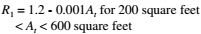
Subject to the limitations of Sections 1607.10.1.1 through 1607.10.1.3 and Table 1607.1, members for which a value of KLLAT is 400 square feet (37.16 m2) or more are permitted to be designed for a reduced uniformly distributed live load, L, in accordance with the following equation:
 (Equation 16-23)
For SI:
where:
| L | = | Reduced design live load per square foot (m2) of area supported by the member. |
| Lo | = | Unreduced design live load per square foot (m2) of area supported by the member (see Table 1607.1). |
| KLL | = | Live load element factor (see Table 1607.10.1). |
| AT | = | Tributary area, in square feet (m2). |
L shall be not less than 0.50Lo for members supporting one floor and L shall be not less than 0.40Lo for members supporting two or more floors.
TABLE 1607.10.1
LIVE LOAD ELEMENT FACTOR, KLL
| ELEMENT | KLL |
| Interior columns | 4 |
| Exterior columns without cantilever slabs | 4 |
| Edge columns with cantilever slabs | 3 |
| Corner columns with cantilever slabs | 2 |
| Edge beams without cantilever slabs | 2 |
| Interior beams | 2 |
| All other members not identified above including: | 1 |
| Edge beams with cantilever slabs | |
| Cantilever beams | |
| One-way slabs | |
| Two-way slabs | |
| Members without provisions for continuous shear transfer normal to their span |
The tributary area, AT, for use in Equation 16-23 for one-way slabs shall not exceed an area defined by the slab span times a width normal to the span of 1.5 times the slab span.
Live loads that exceed 100 psf (4.79 kN/m2) shall not be reduced.
Exceptions:
The live loads shall not be reduced in passenger vehicle garages.
Exception: The live loads for members supporting two or more floors are permitted to be reduced by a maximum of 20 percent, but the live load shall not be less than L as calculated in Section 1607.10.1.
As an alternative to Section 1607.10.1 and subject to the limitations of Table 1607.1, uniformly distributed live loads are permitted to be reduced in accordance with the following provisions. Such reductions shall apply to slab systems, beams, girders, columns, piers, walls and foundations.
 (Equation 16-24)
For SI: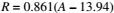
Such reduction shall not exceed the smallest of:
 (Equation 16-25)
where:
| A | = | Area of floor supported by the member, square feet (m2). |
| D | = | Dead load per square foot (m2) of area supported. |
| Lo | = | Unreduced live load per square foot (m2) of area supported. |
| R | = | Reduction in percent. |
Where uniform floor live loads are involved in the design of structural members arranged so as to create continuity, the minimum applied loads shall be the full dead loads on all spans in combination with the floor live loads on spans selected to produce the greatest load effect at each location under consideration. Floor live loads are permitted to be reduced in accordance with Section 1607.10.
The structural supports of roofs and marquees shall be designed to resist wind and, where applicable, snow and earthquake loads, in addition to the dead load of construction and the appropriate live loads as prescribed in this section, or as set forth in Table 1607.1. The live loads acting on a sloping surface shall be assumed to act vertically on the horizontal projection of that surface.
Where uniform roof live loads are reduced to less than 20 psf (0.96 kN/m2) in accordance with Section 1607.12.2.1 and are applied to the design of structural members arranged so as to create continuity, the reduced roof live load shall be applied to adjacent spans or to alternate spans, whichever produces the most unfavorable load effect. See Section 1607.12.2 for reductions in minimum roof live loads and Section 7.5 of ASCE 7 for partial snow loading.
The minimum uniformly distributed live loads of roofs and marquees, Lo, in Table 1607.1 are permitted to be reduced in accordance with Section 1607.12.2.1.
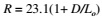
Ordinary flat, pitched and curved roofs, and awnings and canopies other than of fabric construction supported by a skeleton structure, are permitted to be designed for a reduced uniformly distributed roof live load, Lr, as specified in the following equations or other controlling combinations of loads as specified in Section 1605, whichever produces the greater load effect.
In structures such as greenhouses, where special scaffolding is used as a work surface for workers and materials during maintenance and repair operations, a lower roof load than specified in the following equations shall not be used unless approved by the building official. Such structures shall be designed for a minimum roof live load of 12 psf (0.58 kN/m2).
 (Equation 16-26)

For SI:
where:
| Lo | = | Unreduced roof live load per square foot (m2) of horizontal projection supported by the member (see Table 1607.1). |
| Lr | = | Reduced roof live load per square foot (m2) of horizontal projection supported by the member. |
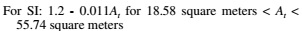
The reduction factors R1 and R2 shall be determined as follows:
 (Equation 16-27)
 (Equation 16-28)
 (Equation 16-29)
where:
| At | = | Tributary area (span length multiplied by effective width) in square feet (m2) supported by the member, and |
 (Equation 16-30)
 (Equation 16-31)
 (Equation 16-32)
where:
| F | = | For a sloped roof, the number of inches of rise per foot (for SI: F = 0.12 × slope, with slope expressed as a percentage), or for an arch or dome, the rise-to-span ratio multiplied by 32. |
Areas of roofs that are occupiable, such as vegetative roofs, roof gardens or for assembly or other similar purposes, and marquees are permitted to have their uniformly distributed live loads reduced in accordance with Section 1607.10.
The weight of all landscaping materials shall be considered as dead load and shall be computed on the basis of saturation of the soil as determined in accordance with ASTM E2397. The uniform design live load in unoccupied landscaped areas on roofs shall be 20 psf (0.958 kN/m2). The uniform design live load for occupied landscaped areas on roofs shall be determined in accordance with Table 1607.1.
Awnings and canopies shall be designed for uniform live loads as required in Table 1607.1 as well as for snow loads and wind loads as specified in Sections 1608 and 1609.
Roof structures that provide support for photovoltaic panel systems shall be designed in accordance with Sections 1607.12.5.1 through 1607.12.5.4, as applicable.
Roof surfaces to be covered by solar photovoltaic panels or modules shall be designed for the roof live load, Lr, assuming that the photovoltaic panels or modules are not present. The roof photovoltaic live load in areas covered by solar photovoltaic panels or modules shall be in addition to the panel loading unless the area covered by each solar photovoltaic panel or module is inaccessible. Areas where the clear space between the panels and the rooftop is not more than 24 inches (610 mm) shall be considered inaccessible. Roof surfaces not covered by photovoltaic panels shall be designed for the roof live load.
The structure of a roof that supports solar photovoltaic panels or modules shall be designed to accommodate the full solar photovoltaic panels or modules and ballast dead load, including concentrated loads from support frames in combination with the loads from Section 1607.12.5.1 and other applicable loads. Where applicable, snow drift loads created by the photovoltaic panels or modules shall be included.
Solar photovoltaic panels or modules that are independent structures and do not have accessible/occupied space underneath are not required to accommodate a roof photovoltaic live load, provided the area under the structure is restricted to keep the public away. All other loads and combinations in accordance with Section 1605 shall be accommodated.
Solar photovoltaic panels or modules that are designed to be the roof, span to structural supports and have accessible/occupied space underneath shall have the panels or modules and all supporting structures designed to support a roof photovoltaic live load, as defined in Section 1607.12.5.1 in combination with other applicable loads. Solar photovoltaic panels or modules in this application are not permitted to be classified as “not accessible” in accordance with Section 1607.12.5.1.
Roof structures that provide support for ballasted photovoltaic panel systems shall be designed, or analyzed, in accordance with Section 1604.4; checked in accordance with Section 1604.3.6 for deflections; and checked in accordance with Section 1611 for ponding.
The crane live load shall be the rated capacity of the crane. Design loads for the runway beams, including connections and support brackets, of moving bridge cranes and monorail cranes shall include the maximum wheel loads of the crane and the vertical impact, lateral and longitudinal forces induced by the moving crane.
The maximum wheel loads shall be the wheel loads produced by the weight of the bridge, as applicable, plus the sum of the rated capacity and the weight of the trolley with the trolley positioned on its runway at the location where the resulting load effect is maximum.
The maximum wheel loads of the crane shall be increased by the percentages shown below to determine the induced vertical impact or vibration force:
| Monorail cranes (powered) | 25 percent |
| Cab-operated or remotely operated bridge cranes (powered) | 25 percent |
| Pendant-operated bridge cranes (powered) | 10 percent |
| Bridge cranes or monorail cranes with hand-geared bridge, trolley and hoist | 0 percent |
The lateral force on crane runway beams with electrically powered trolleys shall be calculated as 20 percent of the sum of the rated capacity of the crane and the weight of the hoist and trolley. The lateral force shall be assumed to act horizontally at the traction surface of a runway beam, in either direction perpendicular to the beam, and shall be distributed with due regard to the lateral stiffness of the runway beam and supporting structure.
The longitudinal force on crane runway beams, except for bridge cranes with hand-geared bridges, shall be calculated as 10 percent of the maximum wheel loads of the crane. The longitudinal force shall be assumed to act horizontally at the traction surface of a runway beam, in either direction parallel to the beam.
Interior walls and partitions that exceed 6 feet (1829 mm) in height, including their finish materials, shall have adequate strength and stiffness to resist the loads to which they are subjected but not less than a horizontal load of 5 psf (0.240 kN/m2).
Fabric partitions that exceed 6 feet (1829 mm) in height, including their finish materials, shall have adequate strength and stiffness to resist the following load conditions:
Design snow loads shall be determined in accordance with Chapter 7 of ASCE 7, but the design roof load shall not be less than that determined by Section 1607.
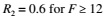
The ground snow loads to be used in determining the design snow loads for roofs shall be determined in accordance with ASCE 7 or Figure 1608.2 for the contiguous United States and Table 1608.2 for Alaska. Site-specific case studies shall be made in areas designated “CS” in Figure 1608.2. Ground snow loads for sites at elevations above the limits indicated in Figure 1608.2 and for all sites within the CS areas shall be approved. Ground snow load determination for such sites shall be based on an extreme value statistical analysis of data available in the vicinity of the site using a value with a 2-percent annual probability of being exceeded (50-year mean recurrence interval). Snow loads are zero for Hawaii, except in mountainous regions as approved by the building official.
TABLE 1608.2
GROUND SNOW LOADS, pg, FOR ALASKAN LOCATIONS
| LOCATION | POUNDS PER SQUARE FOOT | LOCATION | POUNDS PER SQUARE FOOT | LOCATION | POUNDS PER SQUARE FOOT | ||
| Adak | 30 | Galena | 60 | Petersburg | 150 | ||
| Anchorage | 50 | Gulkana | 70 | St. Paul Islands | 40 | ||
| Angoon | 70 | Homer | 40 | Seward | 50 | ||
| Barrow | 25 | Juneau | 60 | Shemya | 25 | ||
| Barter Island | 35 | Kenai | 70 | Sitka | 50 | ||
| Bethel | 40 | Kodiak | 30 | Talkeetna | 120 | ||
| Big Delta | 50 | Kotzebue | 60 | Unalakleet | 50 | ||
| Cold Bay | 25 | McGrath | 70 | Valdez | 160 | ||
| Cordova | 100 | Nenana | 80 | Whittier | 300 | ||
| Fairbanks | 60 | Nome | 70 | Wrangell | 60 | ||
| Fort Yukon | 60 | Palmer | 50 | Yakutat | 150 |
For SI: 1 pound per square foot = 0.0479 kN/m2.
Susceptible bays of roofs shall be evaluated for ponding instability in accordance with Section 7.11 of ASCE 7.
Buildings, structures and parts thereof shall be designed to withstand the minimum wind loads prescribed herein. Decreases in wind loads shall not be made for the effect of shielding by other structures.
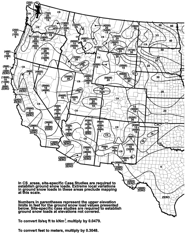
Wind loads on every building or structure shall be determined in accordance with Chapters 26 to 30 of ASCE 7 or provisions of the alternate all-heights method in Section 1609.6. The type of opening protection required, the ultimate design wind speed, Vult, and the exposure category for a site is permitted to be determined in accordance with Section 1609 or ASCE 7. Wind shall be assumed to come from any horizontal direction and wind pressures shall be assumed to act normal to the surface considered.
Exceptions:
The wind speeds in Figures 1609.3(1), 1609.3(2) and 1609.3(3) are ultimate design wind speeds, Vult, and shall be converted in accordance with Section 1609.3.1 to nominal design wind speeds, Vasd, when the provisions of the standards referenced in Exceptions 4 and 5 are used.
The provisions of ICC 600 are applicable only to buildings located within Exposure B or C as defined in Section 1609.4. The provisions of ICC 600, AWC WFCM and AISI S230 shall not apply to buildings sited on the upper half of an isolated hill, ridge or escarpment meeting the following conditions:
In wind-borne debris regions, glazing in buildings shall be impact resistant or protected with an impact-resistant covering meeting the requirements of an approved impact-resistant standard or ASTM E1996 and ASTM E1886 referenced herein as follows:
Exceptions:
TABLE 1609.1.2
WIND-BORNE DEBRIS PROTECTION FASTENING SCHEDULE FOR WOOD STRUCTURAL PANELSa, b, c, d
| FASTENER TYPE | FASTENER SPACING (inches) | ||
| Panel Span ≤ 4 feet | 4 feet < Panel Span ≤ 6 feet | 6 feet < Panel Span ≤ 8 feet | |
| No. 8 wood-screw-based anchor with 2-inch embedment length | 16 | 10 | 8 |
| No. 10 wood-screw-based anchor with 2-inch embedment length | 16 | 12 | 9 |
| 1/4-inch diameter lag-screw-based anchor with 2-inch embedment length | 16 | 16 | 16 |
For SI: 1 inch = 25.4 mm, 1 foot = 304.8 mm, 1 pound = 4.448 N, 1 mile per hour = 0.447 m/s.
Louvers protecting intake and exhaust ventilation ducts not assumed to be open that are located within 30 feet (9144 mm) of grade shall meet the requirements of AMCA 540.
The text of Section 6.2.2 of ASTM E1996 shall be substituted as follows:
Garage door glazed opening protection for wind-borne debris shall meet the requirements of an approved impact-resisting standard or ANSI/DASMA 115.
For the purposes of Section 1609 and as used elsewhere in this code, the following terms are defined in Chapter 2.
HURRICANE-PRONE REGIONS.
WIND-BORNE DEBRIS REGION.
WIND SPEED, Vult.
WIND SPEED, Vasd.
The ultimate design wind speed, Vult, in mph, for the determination of the wind loads shall be determined by Figures 1609.3(1), 1609.3(2) and 1609.3(3). The ultimate design wind speed, Vult, for use in the design of Risk Category II buildings and structures shall be obtained from Figure 1609.3(1). The ultimate design wind speed, Vult, for use in the design of Risk Category III and IV buildings and structures shall be obtained from Figure 1609.3(2). The ultimate design wind speed, Vult, for use in the design of Risk Category I buildings and structures shall be obtained from Figure 1609.3(3). The ultimate design wind speed, Vult, for the special wind regions indicated near mountainous terrain and near gorges shall be in accordance with local jurisdiction requirements. The ultimate design wind speeds, Vult, determined by the local jurisdiction shall be in accordance with Section 26.5.1 of ASCE 7.
In nonhurricane-prone regions, when the ultimate design wind speed, Vult, is estimated from regional climatic data, the ultimate design wind speed, Vult, shall be determined in accordance with Section 26.5.3 of ASCE 7.
When required, the ultimate design wind speeds of Figures 1609.3(1), 1609.3(2) and 1609.3(3) shall be converted to nominal design wind speeds, Vasd, using Table 1609.3.1 or Equation 16-33.
 (Equation 16-33)
where:
| Vasd | = | Nominal design wind speed applicable to methods specified in Exceptions 4 and 5 of Section 1609.1.1. |
| Vult | = | Ultimate design wind speeds determined from Figures 1609.3(1), 1609.3(2) or 1609.3(3). |
TABLE 1609.3.1
WIND SPEED CONVERSIONSa, b, c
| Vult | 100 | 110 | 120 | 130 | 140 | 150 | 160 | 170 | 180 | 190 | 200 |
| Vasd | 78 | 85 | 93 | 101 | 108 | 116 | 124 | 132 | 139 | 147 | 155 |
For SI: 1 mile per hour = 0.44 m/s.
For each wind direction considered, an exposure category that adequately reflects the characteristics of ground surface irregularities shall be determined for the site at which the building or structure is to be constructed. Account shall be taken of variations in ground surface roughness that arise from natural topography and vegetation as well as from constructed features.
For each selected wind direction at which the wind loads are to be evaluated, the exposure of the building or structure shall be determined for the two upwind sectors extending 45 degrees (0.79 rad) either side of the selected wind direction. The exposures in these two sectors shall be determined in accordance with Sections 1609.4.2 and 1609.4.3 and the exposure resulting in the highest wind loads shall be used to represent winds from that direction.
A ground surface roughness within each 45-degree (0.79 rad) sector shall be determined for a distance upwind of the site as defined in Section 1609.4.3 from the categories defined below, for the purpose of assigning an exposure category as defined in Section 1609.4.3.
Surface Roughness B. Urban and suburban areas, wooded areas or other terrain with numerous closely spaced obstructions having the size of single-family dwellings or larger.
Surface Roughness C. Open terrain with scattered obstructions having heights generally less than 30 feet (9144 mm). This category includes flat open country, and grasslands.
Surface Roughness D. Flat, unobstructed areas and water surfaces. This category includes smooth mud flats, salt flats and unbroken ice.
An exposure category shall be determined in accordance with the following:
Exposure B. For buildings with a mean roof height of less than or equal to 30 feet (9144 mm), Exposure B shall apply where the ground surface roughness, as defined by Surface Roughness B, prevails in the upwind direction for a distance of at least 1,500 feet (457 m). For buildings with a mean roof height greater than 30 feet (9144 mm), Exposure B shall apply where Surface Roughness B prevails in the upwind direction for a distance of at least 2,600 feet (792 m) or 20 times the height of the building, whichever is greater.
Exposure C. Exposure C shall apply for all cases where Exposure B or D does not apply.
Exposure D. Exposure D shall apply where the ground surface roughness, as defined by Surface Roughness D, prevails in the upwind direction for a distance of at least 5,000 feet (1524 m) or 20 times the height of the building, whichever is greater. Exposure D shall also apply where the ground surface roughness immediately upwind of the site is B or C, and the site is within a distance of 600 feet (183 m) or 20 times the building height, whichever is greater, from an Exposure D condition as defined in the previous sentence.
Roof systems shall be designed and constructed in accordance with Sections 1609.5.1 through 1609.5.3, as applicable.
The roof deck shall be designed to withstand the wind pressures determined in accordance with ASCE 7.
Roof coverings shall comply with Section 1609.5.1.
Exception: Rigid tile roof coverings that are air permeable and installed over a roof deck complying with Section 1609.5.1 are permitted to be designed in accordance with Section 1609.5.3.
Asphalt shingles installed over a roof deck complying with Section 1609.5.1 shall comply with the wind-resistance requirements of Section 1504.1.1.
Wind loads on rigid tile roof coverings shall be determined in accordance with the following equation:
 (Equation 16-34)
For SI:
where:
| b | = | Exposed width, feet (mm) of the roof tile. |
| CL | = | Lift coefficient. The lift coefficient for concrete and clay tile shall be 0.2 or shall be determined by test in accordance with Section 1504.2.1. |
| GCp | = | Roof pressure coefficient for each applicable roof zone determined from Chapter 30 of ASCE 7. Roof coefficients shall not be adjusted for internal pressure. |
| L | = | Length, feet (mm) of the roof tile. |
| La | = | Moment arm, feet (mm) from the axis of rotation to the point of uplift on the roof tile. The point of uplift shall be taken at 0.76L from the head of the tile and the middle of the exposed width. For roof tiles with nails or screws (with or without a tail clip), the axis of rotation shall be taken as the head of the tile for direct deck application or as the top edge of the batten for battened applications. For roof tiles fastened only by a nail or screw along the side of the tile, the axis of rotation shall be determined by testing. For roof tiles installed with battens and fastened only by a clip near the tail of the tile, the moment arm shall be determined about the top edge of the batten with consideration given for the point of rotation of the tiles based on straight bond or broken bond and the tile profile. |
| Ma | = | Aerodynamic uplift moment, feet-pounds (N-mm) acting to raise the tail of the tile. |
| qh | = | Wind velocity pressure, psf (kN/m2) determined from Section 27.3.2 of ASCE 7. |
Concrete and clay roof tiles complying with the following limitations shall be designed to withstand the aerodynamic uplift moment as determined by this section.
The alternate wind design provisions in this section are simplifications of the ASCE 7 Directional Procedure.
As an alternative to ASCE 7 Chapters 27 and 30, the following provisions are permitted to be used to determine the wind effects on regularly shaped buildings, or other structures that are regularly shaped, that meet all of the following conditions:
The following modifications shall be made to certain subsections in ASCE 7: in Section 1609.6.2, symbols and notations that are specific to this section are used in conjunction with the symbols and notations in ASCE 7 Section 26.3.
Coefficients and variables used in the alternative all-heights method equations are as follows:
| Cnet | = | Net-pressure coefficient based on Kd [(G) (Cp) – (GCpi)], in accordance with Table 1609.6.2. |
| G | = | Gust effect factor for rigid structures in accordance with ASCE 7 Section 26.9.1. |
| Kd | = | Wind directionality factor in accordance with ASCE 7 Table 26-6. |
| Pnet | = | Design wind pressure to be used in determination of wind loads on buildings or other structures or their components and cladding, in psf (kN/m2). |
TABLE 1609.6.2
NET PRESSURE COEFFICIENTS, Cneta, b
| STRUCTURE OR PART THEREOF | DESCRIPTION | Cnet FACTOR | |||
| 1. Main windforce-resisting frames and systems | Walls: | Enclosed | Partially enclosed | ||
| + Internal pressure | – Internal pressure | + Internal pressure | – Internal pressure | ||
| Windward wall | 0.43 | 0.73 | 0.11 | 1.05 | |
| Leeward wall | -0.51 | -0.21 | -0.83 | 0.11 | |
| Sidewall | -0.66 | -0.35 | -0.97 | -0.04 | |
| Parapet wall | Windward | 1.28 | 1.28 | ||
| Leeward | -0.85 | -0.85 | |||
| Roofs: | Enclosed | Partially enclosed | |||
| Wind perpendicular to ridge | + Internal pressure | – Internal pressure | + Internal pressure | – Internal pressure | |
| Leeward roof or flat roof | -0.66 | -0.35 | -0.97 | -0.04 | |
| Windward roof slopes: | |||||
| Slope < 2:12 (10°) | Condition 1 | -1.09 | -0.79 | -1.41 | -0.47 |
| Condition 2 | -0.28 | 0.02 | -0.60 | 0.34 | |
| Slope = 4:12 (18°) | Condition 1 | -0.73 | -0.42 | -1.04 | -0.11 |
| Condition 2 | -0.05 | 0.25 | -0.37 | 0.57 | |
| Slope = 5:12 (23°) | Condition 1 | -0.58 | -0.28 | -0.90 | 0.04 |
| Condition 2 | 0.03 | 0.34 | -0.29 | 0.65 | |
| Slope = 6:12 (27°) | Condition 1 | -0.47 | -0.16 | -0.78 | 0.15 |
| Condition 2 | 0.06 | 0.37 | -0.25 | 0.68 | |
| Slope = 7:12 (30°) | Condition 1 | -0.37 | -0.06 | -0.68 | 0.25 |
| Condition 2 | 0.07 | 0.37 | -0.25 | 0.69 | |
| Slope = 9:12 (37°) | Condition 1 | -0.27 | 0.04 | -0.58 | 0.35 |
| Condition 2 | 0.14 | 0.44 | -0.18 | 0.76 | |
| Slope = 12:12 (45°) | 0.14 | 0.44 | -0.18 | 0.76 | |
| Wind parallel to ridge and flat roofs | -1.09 | -0.79 | -1.41 | -0.47 | |
| Nonbuilding Structures: Chimneys, Tanks and Similar Structures: | |||||
| h/D | |||||
| 1 | 7 | 25 | |||
| Square (Wind normal to face) | 0.99 | 1.07 | 1.53 | ||
| Square (Wind on diagonal) | 0.77 | 0.84 | 1.15 | ||
| Hexagonal or octagonal | 0.81 | 0.97 | 1.13 | ||
| Round | 0.65 | 0.81 | 0.97 | ||
| Open signs and lattice frameworks | Ratio of solid to gross area | ||||
| < 0.1 | 0.1 to 0.29 | 0.3 to 0.7 | |||
| Flat | 1.45 | 1.30 | 1.16 | ||
| Round | 0.87 | 0.94 | 1.08 | ||
| 2. Components and cladding not in areas of discontinuity—roofs and overhangs | Roof elements and slopes | Enclosed | Partially enclosed | ||
| Gable of hipped configurations (Zone 1) | |||||
| Flat < Slope < 6:12 (27°) See ASCE 7 Figure 30.4-2B Zone 1 | |||||
| Positive | 10 square feet or less | 0.58 | 0.89 | ||
| 100 square feet or more | 0.41 | 0.72 | |||
| Negative | 10 square feet or less | -1.00 | -1.32 | ||
| 100 square feet or more | -0.92 | -1.23 | |||
| Overhang: Flat < Slope < 6:12 (27°) See ASCE 7 Figure 30.4-2A Zone 1 | |||||
| Negative | 10 square feet or less | -1.45 | |||
| 100 square feet or more | -1.36 | ||||
| 500 square feet or more | -0.94 | ||||
| 6:12 (27°) < Slope < 12:12 (45°) See ASCE 7 Figure 30.4-2C Zone 1 | |||||
| Positive | 10 square feet or less | 0.92 | 1.23 | ||
| 100 square feet or more | 0.83 | 1.15 | |||
| Negative | 10 square feet or less | -1.00 | -1.32 | ||
| 100 square feet or more | -0.83 | -1.15 | |||
| Monosloped configurations (Zone 1) | Enclosed | Partially enclosed | |||
| Flat < Slope < 7:12 (30°) See ASCE 7 Figure 30.4-5B Zone 1 | |||||
| Positive | 10 square feet or less | 0.49 | 0.81 | ||
| 100 square feet or more | 0.41 | 0.72 | |||
| Negative | 10 square feet or less | -1.26 | -1.57 | ||
| 100 square feet or more | -1.09 | -1.40 | |||
| Tall flat-topped roofs h > 60 feet | Enclosed | Partially enclosed | |||
| Flat < Slope < 2:12 (10°) (Zone 1) See ASCE 7 Figure 30.8-1 Zone 1 | |||||
| Negative | 10 square feet or less | -1.34 | -1.66 | ||
| 500 square feet or more | -0.92 | -1.23 | |||
| 3. Components and cladding in areas of discontinuity—roofs and overhangs (continued) | Gable or hipped configurations at ridges, eaves and rakes (Zone 2) | ||||
| Flat < Slope < 6:12 (27°) See ASCE 7 Figure 30.4-2B Zone 2 | |||||
| Positive | 10 square feet or less | 0.58 | 0.89 | ||
| 100 square feet or more | 0.41 | 0.72 | |||
| Negative | 10 square feet or less | -1.68 | -2.00 | ||
| 100 square feet or more | -1.17 | -1.49 | |||
| Overhang for Slope Flat < Slope < 6:12 (27°) See ASCE 7 Figure 30.4-2B Zone 2 | |||||
| Negative | 10 square feet or less | -1.87 | |||
| 100 square feet or more | -1.87 | ||||
| 6:12 (27°) < Slope < 12:12 (45°) Figure 30.4-2C | Enclosed | Partially enclosed | |||
| Positive | 10 square feet or less | 0.92 | 1.23 | ||
| 100 square feet or more | 0.83 | 1.15 | |||
| Negative | 10 square feet or less | -1.17 | -1.49 | ||
| 100 square feet or more | -1.00 | -1.32 | |||
| Overhang for 6:12 (27°) < Slope < 12:12 (45°) See ASCE 7 Figure 30.4-2C Zone 2 | |||||
| Negative | 10 square feet or less | -1.70 | |||
| 500 square feet or more | -1.53 | ||||
| 3. Components and cladding in areas of discontinuity—roofs and overhangs | Roof elements and slopes | Enclosed | Partially enclosed | ||
| Monosloped configurations at ridges, eaves and rakes (Zone 2) | |||||
| Flat < Slope < 7:12 (30°) See ASCE 7 Figure 30.4-5B Zone 2 | |||||
| Positive | 10 square feet or less | 0.49 | 0.81 | ||
| 100 square feet or more | 0.41 | 0.72 | |||
| Negative | 10 square feet or less | -1.51 | -1.83 | ||
| 100 square feet or more | -1.43 | -1.74 | |||
| Tall flat topped roofs h > 60 feet | Enclosed | Partially enclosed | |||
| Flat < Slope < 2:12 (10°) (Zone 2) See ASCE 7 Figure 30.8-1 Zone 2 | |||||
| Negative | 10 square feet or less | -2.11 | -2.42 | ||
| 500 square feet or more | -1.51 | -1.83 | |||
| Gable or hipped configurations at corners (Zone 3) See ASCE 7 Figure 30.4-2B Zone 3 | |||||
| Flat < Slope < 6:12 (27°) | Enclosed | Partially enclosed | |||
| Positive | 10 square feet or less | 0.58 | 0.89 | ||
| 100 square feet or more | 0.41 | 0.72 | |||
| Negative | 10 square feet or less | -2.53 | -2.85 | ||
| 100 square feet or more | -1.85 | -2.17 | |||
| Overhang for Slope Flat < Slope < 6:12 (27°) See ASCE 7 Figure 30.4-2B Zone 3 | |||||
| Negative | 10 square feet or less | -3.15 | |||
| 100 square feet or more | -2.13 | ||||
| 6:12 (27°) < 12:12 (45°) See ASCE 7 Figure 30.4-2C Zone 3 | |||||
| Positive | 10 square feet or less | 0.92 | 1.23 | ||
| 100 square feet or more | 0.83 | 1.15 | |||
| Negative | 10 square feet or less | -1.17 | -1.49 | ||
| 100 square feet or more | -1.00 | -1.32 | |||
| Overhang for 6:12 (27°) < Slope < 12:12 (45°) | Enclosed | Partially enclosed | |||
| Negative | 10 square feet or less | -1.70 | |||
| 100 square feet or more | -1.53 | ||||
| Monosloped Configurations at corners (Zone 3) See ASCE 7 Figure 30.4-5B Zone 3 | |||||
| Flat < Slope < 7:12 (30°) | |||||
| Positive | 10 square feet or less | 0.49 | 0.81 | ||
| 100 square feet or more | 0.41 | 0.72 | |||
| Negative | 10 square feet or less | -2.62 | -2.93 | ||
| 100 square feet or more | -1.85 | -2.17 | |||
| Tall flat topped roofs h > 60 feet | Enclosed | Partially enclosed | |||
| Flat < Slope < 2:12 (10°) (Zone 3) See ASCE 7 Figure 30.8-1 Zone 3 | |||||
| Negative | 10 square feet or less | -2.87 | -3.19 | ||
| 500 square feet or more | -2.11 | -2.42 | |||
| 4. Components and cladding not in areas of discontinuity—walls and parapets | Wall Elements: h ≤ 60 feet (Zone 4) ASCE 7 Figure 30.4-1 | Enclosed | Partially enclosed | ||
| Positive | 10 square feet or less | 1.00 | 1.32 | ||
| 500 square feet or more | 0.75 | 1.06 | |||
| Negative | 10 square feet or less | -1.09 | -1.40 | ||
| 500 square feet or more | -0.83 | -1.15 | |||
| Wall Elements: h > 60 feet (Zone 4) See ASCE 7 Figure 30.6-1 Zone 4 | |||||
| Positive | 20 square feet or less | 0.92 | 1.23 | ||
| 500 square feet or more | 0.66 | 0.98 | |||
| Negative | 20 square feet or less | -0.92 | -1.23 | ||
| 500 square feet or more | -0.75 | -1.06 | |||
| Parapet Walls | |||||
| Positive | 2.87 | 3.19 | |||
| Negative | -1.68 | -2.00 | |||
| 5. Components and cladding in areas of discontinuity—walls and parapets | Wall elements: h ≤ 60 feet (Zone 5) ASCE 7 Figure 30.4-1 | Enclosed | Partially enclosed | ||
| Positive | 10 square feet or less | 1.00 | 1.32 | ||
| 500 square feet or more | 0.75 | 1.06 | |||
| Negative | 10 square feet or less | -1.34 | -1.66 | ||
| 500 square feet or more | -0.83 | -1.15 | |||
| Wall elements: h > 60 feet (Zone 5) See ASCE 7 Figure 30.6-1 Zone 4 | |||||
| Positive | 20 square feet or less | 0.92 | 1.23 | ||
| 500 square feet or more | 0.66 | 0.98 | |||
| Negative | 20 square feet or less | -1.68 | -2.00 | ||
| 500 square feet or more | -1.00 | -1.32 | |||
| Parapet walls | |||||
| Positive | 3.64 | 3.95 | |||
| Negative | -2.45 | -2.76 |
For SI: 1 foot = 304.8 mm, 1 square foot = 0.0929m2, 1 degree = 0.0175 rad.
When using the alternative all-heights method, the MWFRS, and components and cladding of every structure shall be designed to resist the effects of wind pressures on the building envelope in accordance with Equation 16-35.
 (Equation 16-35)
Design wind forces for the MWFRS shall be not less than 16 psf (0.77 kN/m2) multiplied by the area of the structure projected on a plane normal to the assumed wind direction (see ASCE 7 Section 27.4.7 for criteria). Design net wind pressure for components and cladding shall be not less than 16 psf (0.77 kN/m2) acting in either direction normal to the surface.
The MWFRS and the components and cladding of every building or other structure shall be designed for the pressures calculated using Equation 16-35.
The MWFRS shall be investigated for the torsional effects identified in ASCE 7 Figure 27.4-8.
Velocity pressure exposure coefficient, Kz, shall be determined in accordance with ASCE 7 Section 27.3.1 and the topographic factor, Kzt, shall be determined in accordance with ASCE 7 Section 26.8.
For the design of the MWFRS and for components and cladding, the sum of the internal and external net pressure shall be based on the net pressure coefficient, Cnet.
When using the alternative all-heights method, wind pressures shall be applied simultaneously on, and in a direction normal to, all building envelope wall and roof surfaces.
Wind pressure for each component or cladding element is applied as follows using Cnet values based on the effective wind area, A, contained within the zones in areas of discontinuity of width and/or length “a,” “2a” or “4a” at: corners of roofs and walls; edge strips for ridges, rakes and eaves; or field areas on walls or roofs as indicated in figures in tables in ASCE 7 as referenced in Table 1609.6.2 in accordance with the following:
Foundation walls and retaining walls shall be designed to resist lateral soil loads. Soil loads specified in Table 1610.1 shall be used as the minimum design lateral soil loads unless determined otherwise by a geotechnical investigation in accordance with Section 1803. Foundation walls and other walls in which horizontal movement is restricted at the top shall be designed for at-rest pressure. Retaining walls free to move and rotate at the top shall be permitted to be designed for active pressure. Design lateral pressure from surcharge loads shall be added to the lateral earth pressure load. Design lateral pressure shall be increased if soils at the site are expansive. Foundation walls shall be designed to support the weight of the full hydrostatic pressure of undrained backfill unless a drainage system is installed in accordance with Sections 1805.4.2 and 1805.4.3.
Exception: Foundation walls extending not more than 8 feet (2438 mm) below grade and laterally supported at the top by flexible diaphragms shall be permitted to be designed for active pressure.
TABLE 1610.1
LATERAL SOIL LOAD
| DESCRIPTION OF BACKFILL MATERIALc | UNIFIED SOIL CLASSIFICATION | DESIGN LATERAL SOIL LOADa (pound per square foot per foot of depth) | |
| Active pressure | At-rest pressure | ||
| Well-graded, clean gravels; gravel-sand mixes | GW | 30 | 60 |
| Poorly graded clean gravels; gravel-sand mixes | GP | 30 | 60 |
| Silty gravels, poorly graded gravel-sand mixes | GM | 40 | 60 |
| Clayey gravels, poorly graded gravel-and-clay mixes | GC | 45 | 60 |
| Well-graded, clean sands; gravelly sand mixes | SW | 30 | 60 |
| Poorly graded clean sands; sand-gravel mixes | SP | 30 | 60 |
| Silty sands, poorly graded sand-silt mixes | SM | 45 | 60 |
| Sand-silt clay mix with plastic fines | SM-SC | 45 | 100 |
| Clayey sands, poorly graded sand-clay mixes | SC | 60 | 100 |
| Inorganic silts and clayey silts | ML | 45 | 100 |
| Mixture of inorganic silt and clay | ML-CL | 60 | 100 |
| Inorganic clays of low to medium plasticity | CL | 60 | 100 |
| Organic silts and silt clays, low plasticity | OL | Note b | Note b |
| Inorganic clayey silts, elastic silts | MH | Note b | Note b |
| Inorganic clays of high plasticity | CH | Note b | Note b |
| Organic clays and silty clays | OH | Note b | Note b |
For SI: 1 pound per square foot per foot of depth = 0.157 kPa/m, 1 foot = 304.8 mm.
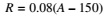
Each portion of a roof shall be designed to sustain the load of rainwater that will accumulate on it if the primary drainage system for that portion is blocked plus the uniform load caused by water that rises above the inlet of the secondary drainage system at its design flow. The design rainfall shall be based on the 100-year hourly rainfall rate indicated in Figure 1611.1 or on other rainfall rates determined from approved local weather data.
 (Equation 16-36)
For SI:
where:
| dh | = | Additional depth of water on the undeflected roof above the inlet of secondary drainage system at its design flow (i.e., the hydraulic head), in inches (mm). |
| ds | = | Depth of water on the undeflected roof up to the inlet of secondary drainage system when the primary drainage system is blocked (i.e., the static head), in inches (mm). |
| R | = | Rain load on the undeflected roof, in psf (kN/m2). When the phrase “undeflected roof” is used, deflections from loads (including dead loads) shall not be considered when determining the amount of rain on the roof. |
Susceptible bays of roofs shall be evaluated for ponding instability in accordance with Section 8.4 of ASCE 7.
Roofs equipped with hardware to control the rate of drainage shall be equipped with a secondary drainage system at a higher elevation that limits accumulation of water on the roof above that elevation. Such roofs shall be designed to sustain the load of rainwater that will accumulate on them to the elevation of the secondary drainage system plus the uniform load caused by water that rises above the inlet of the secondary drainage system at its design flow determined from Section 1611.1. Such roofs shall also be checked for ponding instability in accordance with Section 1611.2.
Within flood hazard areas as established in Section 1612.3, all new construction of buildings, structures and portions of buildings and structures, including substantial improvement and restoration of substantial damage to buildings and structures, shall be designed and constructed to resist the effects of flood hazards and flood loads. For buildings that are located in more than one flood hazard area, the provisions associated with the most restrictive flood hazard area shall apply.
The following terms are defined in Chapter 2:
BASE FLOOD.
BASE FLOOD ELEVATION.
BASEMENT.
COASTAL A ZONE.
COASTAL HIGH HAZARD AREA.
DESIGN FLOOD.
DESIGN FLOOD ELEVATION.
DRY FLOODPROOFING.
EXISTING STRUCTURE.
FLOOD or FLOODING.
FLOOD DAMAGE-RESISTANT MATERIALS.
FLOOD HAZARD AREA.
FLOOD INSURANCE RATE MAP (FIRM).
FLOOD INSURANCE STUDY.
FLOODWAY.
LOWEST FLOOR.
SPECIAL FLOOD HAZARD AREA.
START OF CONSTRUCTION.
SUBSTANTIAL DAMAGE.
SUBSTANTIAL IMPROVEMENT.
To establish flood hazard areas, the applicable governing authority shall adopt a flood hazard map and supporting data. The flood hazard map shall include, at a minimum, areas of special flood hazard as identified by the Federal Emergency Management Agency in an engineering report entitled “The Flood Insurance Study for [INSERT NAME OF JURISDICTION],” dated [INSERT DATE OF ISSUANCE], as amended or revised with the accompanying Flood Insurance Rate Map (FIRM) and Flood Boundary and Floodway Map (FBFM) and related supporting data along with any revisions thereto. The adopted flood hazard map and supporting data are hereby adopted by reference and declared to be part of this section.
Where design flood elevations are not included in the flood hazard areas established in Section 1612.3, or where floodways are not designated, the building official is authorized to require the applicant to:
In riverine flood hazard areas where design flood elevations are specified but floodways have not been designated, the applicant shall provide a floodway analysis that demonstrates that the proposed work will not increase the design flood elevation more than 1 foot (305 mm) at any point within the jurisdiction of the applicable governing authority.
The design and construction of buildings and structures located in flood hazard areas, including coastal high hazard areas and coastal A zones, shall be in accordance with Chapter 5 of ASCE 7 and ASCE 24.
The following documentation shall be prepared and sealed by a registered design professional and submitted to the building official:
Every structure, and portion thereof, including nonstructural components that are permanently attached to structures and their supports and attachments, shall be designed and constructed to resist the effects of earthquake motions in accordance with ASCE 7, excluding Chapter 14 and Appendix 11A. The seismic design category for a structure is permitted to be determined in accordance with Section 1613 or ASCE 7.
Exceptions:
The following terms are defined in Chapter 2:
DESIGN EARTHQUAKE GROUND MOTION.
ORTHOGONAL.
RISK-TARGETED MAXIMUM CONSIDERED EARTHQUAKE (MCER) GROUND MOTION RESPONSE ACCELERATION.
SEISMIC DESIGN CATEGORY.
SEISMIC FORCE-RESISTING SYSTEM.
SITE CLASS.
SITE COEFFICIENTS.
Seismic ground motion values shall be determined in accordance with this section.
The parameters SS and S1 shall be determined from the 0.2 and 1-second spectral response accelerations shown on Figures 1613.3.1(1) through 1613.3.1(8). Where S1 is less than or equal to 0.04 and SS is less than or equal to 0.15, the structure is permitted to be assigned Seismic Design Category A.
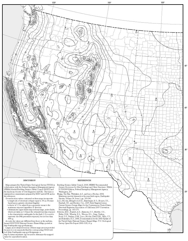
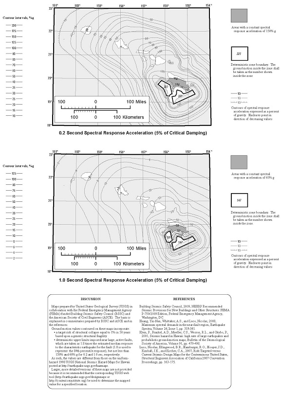
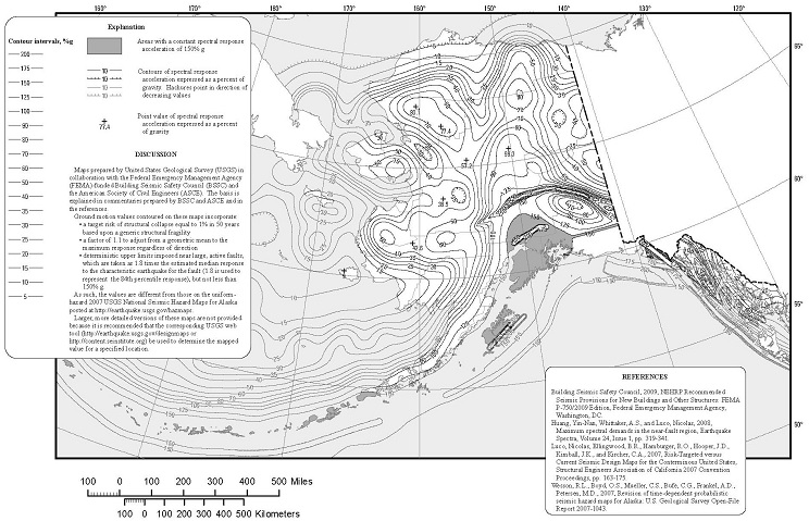
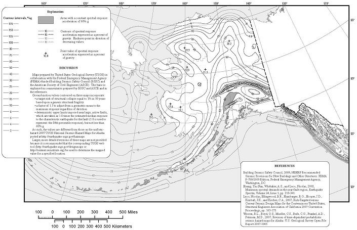
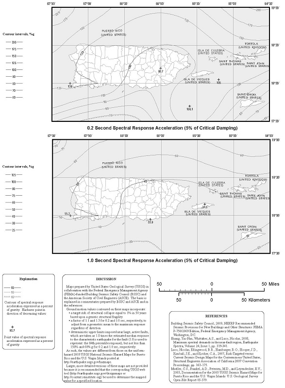
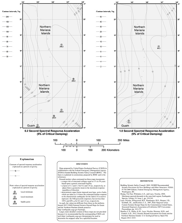
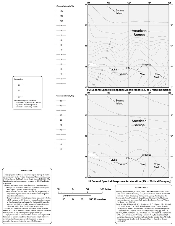
Based on the site soil properties, the site shall be classified as Site Class A, B, C, D, E or F in accordance with Chapter 20 of ASCE 7.
Where the soil properties are not known in sufficient detail to determine the site class, Site Class D shall be used unless the building official or geotechnical data determines Site Class E or F soils are present at the site.
The maximum considered earthquake spectral response acceleration for short periods, SMS, and at 1-second period, SM1, adjusted for site class effects shall be determined by Equations 16-37 and 16-38, respectively:
 (Equation 16-37)
 (Equation 16-38)
where:
| Fa | = | Site coefficient defined in Table 1613.3.3(1). |
| Fv | = | Site coefficient defined in Table 1613.3.3(2). |
| SS | = | The mapped spectral accelerations for short periods as determined in Section 1613.3.1. |
| S1 | = | The mapped spectral accelerations for a 1-second period as determined in Section 1613.3.1. |
TABLE 1613.3.3(1)
VALUES OF SITE COEFFICIENT Faa
| SITE CLASS | MAPPED SPECTRAL RESPONSE ACCELERATION AT SHORT PERIOD | ||||
| Ss ≤ 0.25 | Ss = 0.50 | Ss = 0.75 | Ss = 1.00 | Ss ≥ 1.25 | |
| A | 0.8 | 0.8 | 0.8 | 0.8 | 0.8 |
| B | 1.0 | 1.0 | 1.0 | 1.0 | 1.0 |
| C | 1.2 | 1.2 | 1.1 | 1.0 | 1.0 |
| D | 1.6 | 1.4 | 1.2 | 1.1 | 1.0 |
| E | 2.5 | 1.7 | 1.2 | 0.9 | 0.9 |
| F | Note b | Note b | Note b | Note b | Note b |
TABLE 1613.3.3(2)
VALUES OF SITE COEFFICIENT FV a
| SITE CLASS | MAPPED SPECTRAL RESPONSE ACCELERATION AT 1-SECOND PERIOD | ||||
| S1 ≤ 0.1 | S1 = 0.2 | S1 = 0.3 | S1 = 0.4 | S1 ≥ 0.5 | |
| A | 0.8 | 0.8 | 0.8 | 0.8 | 0.8 |
| B | 1.0 | 1.0 | 1.0 | 1.0 | 1.0 |
| C | 1.7 | 1.6 | 1.5 | 1.4 | 1.3 |
| D | 2.4 | 2.0 | 1.8 | 1.6 | 1.5 |
| E | 3.5 | 3.2 | 2.8 | 2.4 | 2.4 |
| F | Note b | Note b | Note b | Note b | Note b |
Five-percent damped design spectral response acceleration at short periods, SDS, and at 1-second period, SD1, shall be determined from Equations 16-39 and 16-40, respectively:
 (Equation 16-39)
 (Equation 16-40)
where:
| SMS | = | The maximum considered earthquake spectral response accelerations for short period as determined in Section 1613.3.3. |
| SM1 | = | The maximum considered earthquake spectral response accelerations for 1-second period as determined in Section 1613.3.3. |
Structures classified as Risk Category I, II or III that are located where the mapped spectral response acceleration parameter at 1-second period, S1, is greater than or equal to 0.75 shall be assigned to Seismic Design Category E. Structures classified as Risk Category IV that are located where the mapped spectral response acceleration parameter at 1-second period, S1, is greater than or equal to 0.75 shall be assigned to Seismic Design Category F. All other structures shall be assigned to a seismic design category based on their risk category and the design spectral response acceleration parameters, SDS and SD1, determined in accordance with Section 1613.3.4 or the site-specific procedures of ASCE 7. Each building and structure shall be assigned to the more severe seismic design category in accordance with Table 1613.3.5(1) or 1613.3.5(2), irrespective of the fundamental period of vibration of the structure, T.
TABLE 1613.3.5(1)
SEISMIC DESIGN CATEGORY BASED ON SHORT-PERIOD (0.2 second) RESPONSE ACCELERATION
| VALUE OF SDS | RISK CATEGORY | ||
| I or II | III | IV | |
| SDS < 0.167g | A | A | A |
| 0.167g ≤ SDS < 0.33g | B | B | C |
| 0.33g ≤ SDS < 0.50g | C | C | D |
| 0.50g ≤ SDS | D | D | D |
TABLE 1613.3.5(2)
SEISMIC DESIGN CATEGORY BASED ON 1-SECOND PERIOD RESPONSE ACCELERATION
| VALUE OF SD1 | RISK CATEGORY | ||
| I or II | III | IV | |
| SD1 < 0.067g | A | A | A |
| 0.067g ≤ SD1 < 0.133g | B | B | C |
| 0.133g ≤ SD1 < 0.20g | C | C | D |
| 0.20g ≤ SD1 | D | D | D |
Where S1 is less than 0.75, the seismic design category is permitted to be determined from Table 1613.3.5(1) alone when all of the following apply:
Where the alternate simplified design procedure of ASCE 7 is used, the seismic design category shall be determined in accordance with ASCE 7.
The provisions of Section 1613.4 shall be permitted as alternatives to the relevant provisions of ASCE 7.
Add the following exception to the end of Section 17.5.4.2 of ASCE 7:
Exception: For isolated structures designed in accordance with this standard, the structural system limitations including structural height limits, in Table 12.2-1 for ordinary steel concentrically braced frames (OCBFs) as defined in Chapter 11 and ordinary moment frames (OMFs) as defined in Chapter 11 are permitted to be taken as 160 feet (48 768 mm) for structures assigned to Seismic Design Category D, E or F, provided that the following conditions are satisfied:
The provisions of Section 1613.5 shall be permitted as an amendment to the relevant provisions of ASCE 7.
Modify ASCE 7 Section 12.11.2.2.1 as follows:
12.11.2.2.1 Transfer of anchorage forces into diaphragm. Diaphragms shall be provided with continuous ties or struts between diaphragm chords to distribute these anchorage forces into the diaphragms. Diaphragm connections shall be positive, mechanical or welded. Added chords are permitted to be used to form subdiaphragms to transmit the anchorage forces to the main continuous cross-ties. The maximum length-to-width ratio of a wood, wood structural panel or untopped steel deck sheathed structural subdiaphragm that serves as part of the continuous tie system shall be 2.5 to 1. Connections and anchorages capable of resisting the prescribed forces shall be provided between the diaphragm and the attached components. Connections shall extend into the diaphragm a sufficient distance to develop the force transferred into the diaphragm.
Ballasted, roof-mounted photovoltaic panel systems need not be rigidly attached to the roof or supporting structure. Ballasted non-penetrating systems shall be designed and installed only on roofs with slopes not more than one unit vertical in 12 units horizontal. Ballasted nonpenetrating systems shall be designed to resist sliding and uplift resulting from lateral and vertical forces as required by Section 1605, using a coefficient of friction determined by acceptable engineering principles. In structures assigned to Seismic Design Category C, D, E or F, ballasted nonpenetrating systems shall be designed to accommodate seismic displacement determined by nonlinear response-history analysis or shake-table testing, using input motions consistent with ASCE 7 lateral and vertical seismic forces for nonstructural components on roofs.
Ice-sensitive structures shall be designed for atmospheric ice loads in accordance with Chapter 10 of ASCE 7.
High-rise buildings that are assigned to Risk Category III or IV shall comply with the requirements of this section. Frame structures shall comply with the requirements of Section 1615.3. Bearing wall structures shall comply with the requirements of Section 1615.4.
The following words and terms are defined in Chapter 2:
BEARING WALL STRUCTURE.
FRAME STRUCTURE.
Frame structures shall comply with the requirements of this section.
Frame structures constructed primarily of reinforced or prestressed concrete, either cast-in-place or precast, or a combination of these, shall conform to the requirements of Section 4.10 of ACI 318. Where ACI 318 requires that nonprestressed reinforcing or prestressing steel pass through the region bounded by the longitudinal column reinforcement, that reinforcing or prestressing steel shall have a minimum nominal tensile strength equal to two-thirds of the required one-way vertical strength of the connection of the floor or roof system to the column in each direction of beam or slab reinforcement passing through the column.
Exception: Where concrete slabs with continuous reinforcement having an area not less than 0.0015 times the concrete area in each of two orthogonal directions are present and are either monolithic with or equivalently bonded to beams, girders or columns, the longitudinal reinforcing or prestressing steel passing through the column reinforcement shall have a nominal tensile strength of one-third of the required one-way vertical strength of the connection of the floor or roof system to the column in each direction of beam or slab reinforcement passing through the column.
Frame structures constructed with a structural steel frame or a frame composed of open web steel joists, joist girders with or without other structural steel elements or a frame composed of composite steel or composite steel joists and reinforced concrete elements shall conform to the requirements of this section.
Each column splice shall have the minimum design strength in tension to transfer the design dead and live load tributary to the column between the splice and the splice or base immediately below.
End connections of all beams and girders shall have a minimum nominal axial tensile strength equal to the required vertical shear strength for allowable stress design (ASD) or two-thirds of the required shear strength for load and resistance factor design (LRFD) but not less than 10 kips (45 kN). For the purpose of this section, the shear force and the axial tensile force need not be considered to act simultaneously.
Exception: Where beams, girders, open web joist and joist girders support a concrete slab or concrete slab on metal deck that is attached to the beam or girder with not less than 3/8-inch-diameter (9.5 mm) headed shear studs, at a spacing of not more than 12 inches (305 mm) on center, averaged over the length of the member, or other attachment having equivalent shear strength, and the slab contains continuous distributed reinforcement in each of two orthogonal directions with an area not less than 0.0015 times the concrete area, the nominal axial tension strength of the end connection shall be permitted to be taken as half the required vertical shear strength for ASD or one-third of the required shear strength for LRFD, but not less than 10 kips (45 kN).
Bearing wall structures shall have vertical ties in all load-bearing walls and longitudinal ties, transverse ties and perimeter ties at each floor level in accordance with this section and as shown in Figure 1615.4.
Precast bearing wall structures constructed solely of reinforced or prestressed concrete, or combinations of these shall conform to the requirements of Sections 16.2.4 and 16.2.5 of ACI 318.
Ties in bearing wall structures other than those covered in Section 1615.4.1 shall conform to this section.
Longitudinal ties shall consist of continuous reinforcement in slabs; continuous or spliced decks or sheathing; continuous or spliced members framing to, within or across walls; or connections of continuous framing members to walls. Longitudinal ties shall extend across interior load-bearing walls and shall connect to exterior load-bearing walls and shall be spaced at not greater than 10 feet (3038 mm) on center. Ties shall have a minimum nominal tensile strength, TT, given by Equation 16-41. For ASD the minimum nominal tensile strength shall be permitted to be taken as 1.5 times the allowable tensile stress times the area of the tie.
 (Equation 16-41)
where:
| L | = | The span of the horizontal element in the direction of the tie, between bearing walls, feet (m). |
| w | = | The weight per unit area of the floor or roof in the span being tied to or across the wall, psf (N/m2). |
| S | = | The spacing between ties, feet (m). |
| αT | = | A coefficient with a value of 1,500 pounds per foot (2.25 kN/m) for masonry bearing wall structures and a value of 375 pounds per foot (0.6 kN/m) for structures with bearing walls of cold-formed steel light-frame construction. |
Transverse ties shall consist of continuous reinforcement in slabs; continuous or spliced decks or sheathing; continuous or spliced members framing to, within or across walls; or connections of continuous framing members to walls. Transverse ties shall be placed no farther apart than the spacing of load-bearing walls. Transverse ties shall have minimum nominal tensile strength TT, given by Equation 16-41. For ASD the minimum nominal tensile strength shall be permitted to be taken as 1.5 times the allowable tensile stress times the area of the tie.
Perimeter ties shall consist of continuous reinforcement in slabs; continuous or spliced decks or sheathing; continuous or spliced members framing to, within or across walls; or connections of continuous framing members to walls. Ties around the perimeter of each floor and roof shall be located within 4 feet (1219 mm) of the edge and shall provide a nominal strength in tension not less than Tp, given by Equation 16-42. For ASD the minimum nominal tensile strength shall be permitted to be taken as 1.5 times the allowable tensile stress times the area of the tie.
 (Equation 16-42)
For SI:
where:
| w | = | As defined in Section 1615.4.2.1. |
| βT | = | A coefficient with a value of 16,000 pounds (7200 kN) for structures with masonry bearing walls and a value of 4,000 pounds (1300 kN) for structures with bearing walls of cold-formed steel light-frame construction. |
Vertical ties shall consist of continuous or spliced reinforcing, continuous or spliced members, wall sheathing or other engineered systems. Vertical tension ties shall be provided in bearing walls and shall be continuous over the height of the building. The minimum nominal tensile strength for vertical ties within a bearing wall shall be equal to the weight of the wall within that story plus the weight of the diaphragm tributary to the wall in the story below. No fewer than two ties shall be provided for each wall. The strength of each tie need not exceed 3,000 pounds per foot (450 kN/m) of wall tributary to the tie for walls of masonry construction or 750 pounds per foot (140 kN/m) of wall tributary to the tie for walls of cold-formed steel light-frame construction.
Read more